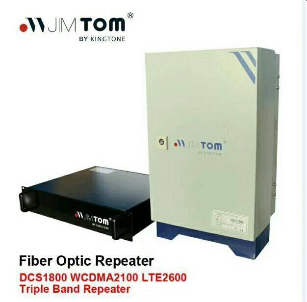
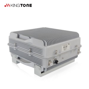
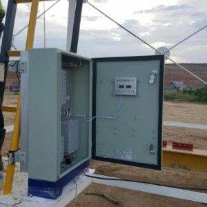
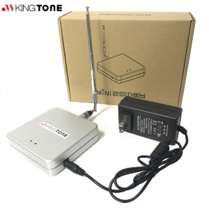
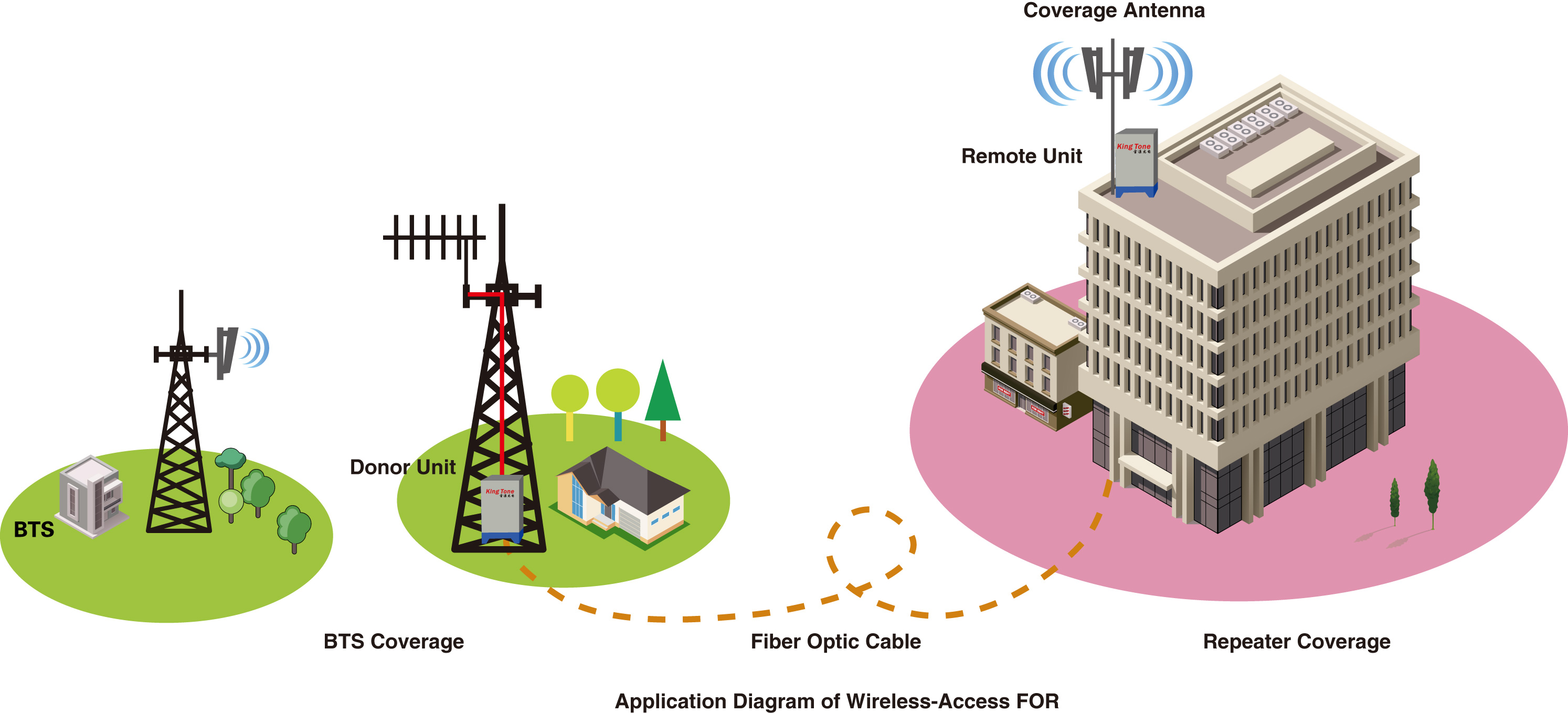
 Kingtone Fiber Optic Repeaters system is designed to solve problems of weak mobile signal, which is much cheaper than setup a new Base Station (BTS).
-
-Main operation of RF Repeaters system:
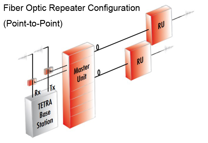
For the down link, signals from BTS is fed to Master Unit(MU), the MU then convert RF signal to laser signal then feed to fiber to transmit to Remote Unit(RU). RU then convert laser signal to RF signal, and use Power Amplifier to amplify to high power to IBS or coverage antenna.
For the uplink, Is a reverse process, signals from user mobile is fed to MU’s MS port. Via duplexer, the signal is amplified by low noise amplifier to improve signal strength. Then the signals is fed to RF fiber optical module then converted to laser signals, then the laser signal is transmit to MU, the laser signal from RU is convert to RF signal by RF optical transceiver. Then the RF signals are amplified to more strength signals fed to BTS.
- Mainfeature
- Main Features◇ High linearity PA; High system gain;
◇ Intelligent ALC technology;
◇ Full duplex and high isolation from uplink to downlink;
◇ Automatic Operation convenient operation;
◇ Integrated technique with reliable performance;
◇ Local and remote monitoring (optional) with automatic fault alarm &remote control;
◇ Weatherproof design for all-weather installation;
- Application&scenarios
- Applications To expand signal coverage of fill signal blind area where signal is weak
or unavailable.
Outdoor: Airports, Tourism Regions, Golf Courses, Tunnels, Factories, Mining Districts, Villages etc.
Indoor: Hotels, Exhibition Centers, Basements, Shopping
Malls, Offices, Packing Lots etc.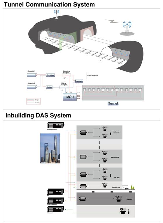
- Specification
-
1.Master Unit Technical Specification
Items
Testing Condition
Technical Specification
Memo
Uplink
Downlink
RF Specifications
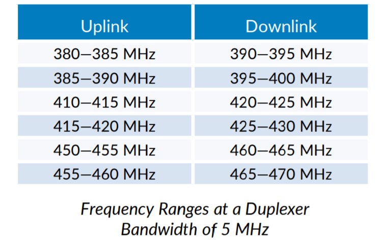
Frequency Range
Working in-band
414-416MHz
424-426MHz
1
Max RF Input level
Working in-band
-
+5dBm
Min RF Input level
Working in-band
-
-70dBm
Max RF input without damage
Working in-band
-
10dBm
VSWR
Working in-band
≤1.5
Connector
N-Female
Optical Specifications
Optical Output Power
-
-3dBm±2dB
Optical Max Input power
+4dBm
-
Optical Min Input power
+0dBm
-
Optical Input damage level
+10dBm
-
Optical length
DL: 1310nm, UL: 1550nm
Optical Loss
≤10dB /Includes the loss of the optical splitter
Optical Connector
FC/APC X 1(WDM, one core)
Nos Of Optical Ports
1
Power Supply and Mechanical Specifications
Power Supply
AC88-264V,45~55Hz
Dimension
435mm*312mm*90mm
Weight
8kg
Max. Power Consumption
50W
Operating Temperature
-20~+55℃
Operating Humidity
≤85%
Environmental Class
IP20
RF Connector
N-Female, 50ohm
MTBF
≥50000 hours
Monitor Interface(optional)
Local Monitor: Remote Monitor: RS232 UMTS modem
Alarm Type
No Power, Over Temperature, RU Failed
2.Remote Unit Technical Specification
Items
Testing Condition
Technical Specification
Uplink
Downlink
RF Specifications
Frequency Range
Working in-band
414-416MHz
424-426MHz
2
Output Power (Max.)
Working in-band
-
43±2dBm(20w)
Max Input without damage
Working in-band
-
+10dBm
Max Input RF level
Working in-band
-
-25dBm
Min Input RF level
Working in-band
-
-107dBm
Noise Figure
Working in-band
-
≤5dB
Gain Adjustable Range/Step
Working in-band
≥25dB/1dB
Gain Adjustable Error
Working in-band
Gain adjustable range is 0~20dB, error≤1dB; ≥21dB, error≤1.5dB
Ripple
Working in-band
≤3dB in bandwidth
IMD3
≤-45dBc
ALC
Working in-band
When adding ≤10dB at max. Output level, output variation ≤±2dB, When adding >10dB, output variation ≤±2dB or be off.
VSWR
Working in-band
≤1.5
Time Delay
Working in-band
≤1.0μs
Spurious Emission
Complies with ETSI TS 101 789-1
Optical Specifications
Optical Output Power
0~3dBm
Optical length
DL: 1310nm, UL: 1550nm
Optical Loss
≤10dB /Includes the loss of the optical splitter
Optical Connector
FC/APC X 1(WDM, one core)
Optical Max input power
+4dBm
Optical Min input power
+0dBm
Optical input power without damage
+10dBm
Power Supply and Mechanical Specifications
Power Supply
AC85-264V,45~55Hz
Dimension
<670mm*420mm*210mm
Weight
<35kg
Max. Power Consumption
150W
Operating Temperature
-25~+55℃
Operating Humidity
≤95%
Environmental Class
IP55
RF Connector
N-Female, 50ohm
MTBF
≥50000 hours
Monitor Interface
Local Monitor: Remote Monitor: RS232 ,GSM modem
Alarm Type
No Power, PA Failure, VSWR, Over Power, Over Temperature


