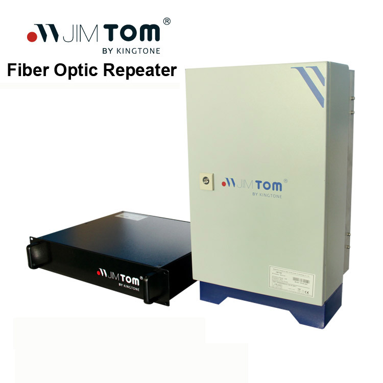
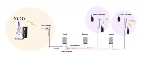
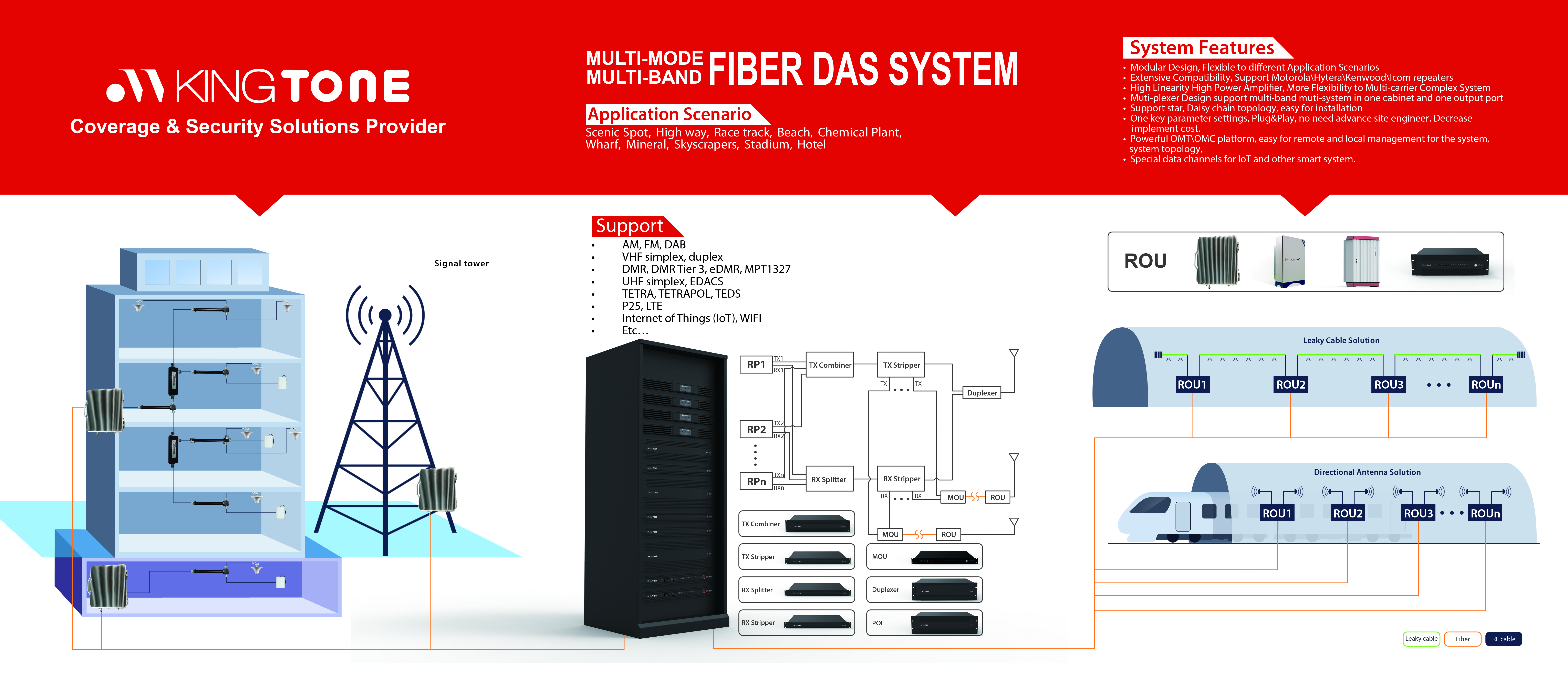
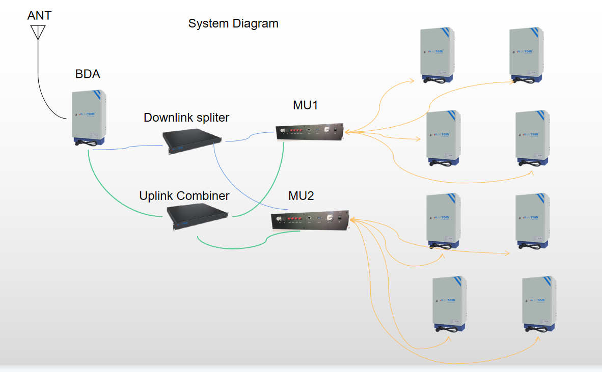
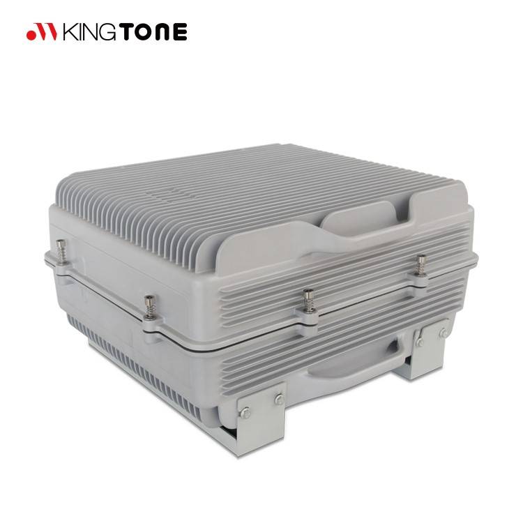
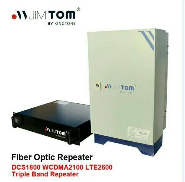
Kingtone JIMTOM® Fiber Optic Repeaters system is designed to solve problems of weak mobile signal, which is much cheaper than setup a new Base Station (BTS). Main operation of RF Repeaters system: For the down link, signals from BTS is fed to Master Unit(MU), the MU then convert RF signal to laser signal then feed to fiber to transmit to Remote Unit(RU). RU then convert laser signal to RF signal, and use Power Amplifier to amplify to high power to IBS or coverage antenna. For the up link, Is a reverse process, signals from user mobile is fed to MU’s MS port. Via duplexer, the signal is amplified by low noise amplifier to improve signal strength. Then the signals is fed to RF fiber optical module then converted to laser signals, then the laser signal is transmit to MU, the laser signal from RU is convert to RF signal by RF optical transceiver. Then the RF signals are amplified to more strength signals fed to BTS.
RF Repeater is designed to enhance cellular network coverage and fill blind spots. Main operation of the repeater is to receive low-power signal from Base Station (BS) via radio frequency (RF) transmission by its donor antenna,process, amplify and forward the signal to Mobile Station (MS) in target coverage area by its service antenna.
Main Features
- FPGA Base SDR technology, Sharpening out of band gain rejection;
- Internal adopt intelligent monitoring, is convenient to locate the faults for maintain;
- Low power consumption, excellent heat dissipation;
- High linearity PA, high system gain;
- Local and remote monitoring (optional) with automatic fault alarm &remote control;
- Compact size, flexible for installation and relocation;
- Weatherproof design for all-weather installation;
- One MU can drive Max 32 RUs, Save cost and ease installation.
- Support ring, daisy chain,star topology, improve network flexibility.
- Multi-carrier design,max 16 carriers,Easily handle high traffic application scenarios
MOU+ROU Whole System Technical Specification
|
Items |
Testing Condition |
Technical Specification |
Memo |
||
|
uplink |
downlink |
||||
|
Frequency Range |
Working in-band |
320MHz~400MHz,400MHz~470MHz |
customized |
||
|
Max Bandwidth |
Working in-band |
5MHz |
|
||
|
Channel Bandwidth |
Working in-band |
25KHz |
|
||
|
Max Chanel Number |
Working in-band |
16 |
|
||
|
Output Power |
Working in-band |
-10±2dBm |
+37±2dBm |
Customized |
|
|
ALC(dB) |
Input add 10dB |
△Po≤±2 |
|
||
|
Max Gain |
Working in-band |
90±3dB |
90±3dB |
|
|
|
Ripple in Band(dB) |
Effective Bandwidth |
≤3 |
|
||
|
Max.input level Without Damage |
Continue 1min |
-10 dBm |
|
||
|
IMD |
In Working band |
2 tones with 75KHz Channel Space |
≤ -45dBc@RBW 30KHz |
|
|
|
8 tones with 75KHz Channel Space |
≤ -40dBc@RBW 30KHz |
|
|||
|
2.5MHz Offset,Outside Working band |
9KHz-1GHz |
-36dBm@RBW100KHz |
|
||
|
1GHz-12.5GHz |
-30dBm@RBW1MHz |
|
|||
|
Carrier out of channel Rejection with 6dB offset |
±50KHz |
≤-20dBc |
|
||
|
±75KHz |
≤-25dBc |
|
|||
|
±125KHz |
≤-30dBc |
|
|||
|
±250KHz |
≤-63dBc |
|
|||
|
±500KHz |
≤-67dBc |
|
|||
|
Transmission Delay(us) |
Working in-band |
≤35.0 |
|
||
|
Noise Figure(dB) |
Working in-band |
≤5(Max.gain) |
|
||
|
Port VSWR |
BS Port |
≤1.5 |
|
||
|
MS Port |
≤1.5 |
||||


