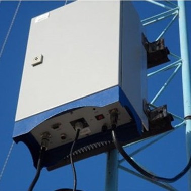
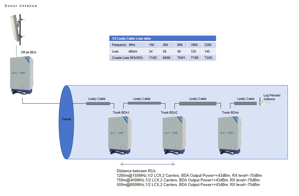
Kingtone JIMTOM® Off-air Tunnel Coverage Solution is designed to solve problems of weak mobile signal, which is much cheaper than setup a new Base Station (BTS). Main Working principle of Repeater system: For the down link, signals from BTS is received by donor antenna and fed to off-air BDA, the off-air BDA then amplified the RF signal to stronger signal then feed to leaky cable to cover the tunnel for the distance 500 meters, then add a trunk BDA re-boost the faded signal to a strong one and then fed to leaky cable to cover the tunnel for 500 meters, if the tunnel is long and need more trunk BDA to cascaded to boost the faded signal to strong one. For the up link, It is a reversed process, signals from user mobile is received by leaky cable is fed to trunk BDA to boost to a strong one then fed to leaky cable to transfer to the cascaded trunk BDA or off-air BDA, At the end of BDA stage, The UL signal is amplified by low noise amplifier of off-air BDA to improve signal strength. Then the UL RF signals are amplified by UL PA of off-air BDA to more strength signals and re-transmit to BTS via donor antenna.
Main Features
◇ Compatible with TETRA, TETRAPOL, P25 (Ph1 and Ph2),PDT,DMR
◇ High level, high availability, convenient for maintenance;
◇ Low power consumption, excellent heat dissipation;
◇ High linearity PA, high system gain;
◇ Local and remote monitoring (optional) with automatic fault alarm &remote control;
◇ Compact size, flexible for installation and relocation;
◇ Waterproof design for all-weather installation;
System Diagram
|
Items |
Testing Condition |
Technical Specification |
Memo |
||||
|
|
|
Uplink |
Downlink |
|
|||
|
Frequency Range |
Working in-band |
147-149MHz |
161~163MHz |
Customizable |
|||
|
Duplex Space |
Working in-band |
13.45MHz |
Customizable |
||||
|
Max Bandwidth |
Working in-band |
2MHz |
|
||||
|
Output Power |
Working in-band |
+30±2 dBm |
+43±2 dBm |
Customizable |
|||
|
Max Gain |
Working in-band |
85±3 dB |
90±3 dB |
Customizable |
|||
|
IMD |
Working in-band |
≤-45dBc |
≤-45dBc |
|
|||
|
Delay |
Working in-band |
≤1uS |
≤1uS |
|
|||
|
Spurious emissions |
9 kHz to 1 GHz |
|
≤ -36 dBm (250 nW) |
|
|||
|
|
1 GHz to 12,75 GHz |
|
≤ -30 dBm (1μW) |
|
|||
|
Max RF Input level |
Working in-band |
- |
+5dBm |
|
|||
|
Min RF Input level |
Working in-band |
- |
-70dBm |
|
|||
|
Max RF input without damage |
Working in-band |
- |
10dBm |
|
|||
|
VSWR |
Working in-band |
≤1.5 |
|
||||
|
Impedance |
Working in-band |
50Ω |
|
||||
|
Connector |
DL RF Input |
Working in-band |
N-Female |
|
|||
|
|
UL RF Output |
Working in-band |
N-Female |
|
|||
|
Power Supply and Mechanical Specifications |
|||||||
|
Power Supply |
|
AC220V |
|
||||
|
Dimension |
|
530mm*310mm*175mm |
|
||||
|
Weight |
|
30kg |
|
||||
|
Max. Power Consumption |
|
≤ 200W @Total |
|
||||
|
Operating Temperature |
|
-5~+75℃ |
|
||||
|
Storage Temperature |
|
-5~+75℃ |
|
||||
|
Operating Humidity |
|
≤95% |
|
||||
|
Environmental Class |
|
IP55 |
|
||||
|
RF Connector |
|
N-Female, 50ohm |
|
||||
|
MTBF |
|
≥50000 hours |
|
||||
|
Power LED |
|
Power Indicator |
|
||||
|
Alarm LED |
|
Alarm Indicator |
|||||
Applications
To expand signal coverage of fill signal blind area where signal is weak or unavailable.
Outdoor: Airports, Tourism Regions, Golf Courses, Tunnels, Factories, Mining Districts, Villages etc.
Indoor: Control room, CTP building,Hotels, Exhibition Centers, Basements, Shopping Malls, Offices, Packing Lots etc.
Off-air BDA Technical Specification
|
Items |
Testing Condition |
Technical Specification |
Memo |
||||
|
Uplink |
Downlink |
|
|||||
|
Frequency Range |
Working in-band |
147-149MHz |
161~163MHz |
Customizable |
|||
|
Duplex Space |
Working in-band |
13.45MHz |
Customizable |
||||
|
Max Bandwidth |
Working in-band |
2MHz |
|
||||
|
Output Power |
Working in-band |
+30±2 dBm |
+43±2 dBm |
Customizable |
|||
|
Max Gain |
Working in-band |
85±3 dB |
90±3 dB |
Customizable |
|||
|
IMD |
Working in-band |
≤-45dBc |
≤-45dBc |
|
|||
|
Delay |
Working in-band |
≤1uS |
≤1uS |
|
|||
|
Spurious emissions |
9 kHz to 1 GHz |
|
≤ -36 dBm (250 nW) |
|
|||
|
1 GHz to 12,75 GHz |
|
≤ -30 dBm (1μW) |
|
||||
|
Max RF Input level |
Working in-band |
- |
+5dBm |
|
|||
|
Min RF Input level |
Working in-band |
- |
-70dBm |
|
|||
|
Max RF input without damage |
Working in-band |
- |
10dBm |
|
|||
|
VSWR |
Working in-band |
≤1.5 |
|
||||
|
Impedance |
Working in-band |
50Ω |
|
||||
|
Connector |
DL RF Input |
Working in-band |
N-Female |
|
|||
|
UL RF Output |
Working in-band |
N-Female |
|
||||
|
Power Supply and Mechanical Specifications |
|||||||
|
Power Supply |
|
AC220V |
|
||||
|
Dimension |
|
530mm*310mm*175mm |
|
||||
|
Weight |
|
30kg |
|
||||
|
Max. Power Consumption |
|
≤ 200W @Total |
|
||||
|
Operating Temperature |
|
-5~+75℃ |
|
||||
|
Storage Temperature |
|
-5~+75℃ |
|
||||
|
Operating Humidity |
|
≤95% |
|
||||
|
Environmental Class |
|
IP55 |
|
||||
|
RF Connector |
|
N-Female, 50ohm |
|
||||
|
MTBF |
|
≥50000 hours |
|
||||
|
Power LED |
|
Power Indicator |
|
||||
|
Alarm LED |
|
Alarm Indicator |
|||||


